 |
* Questions are answered in 1-2 business days. * Questions may be published (We do not post email addresses) * Spammers will be blocked |
Alert Link Nurse Call Pull Cord Interface
Home > Patient Safety > Alarms & Pads > Alert Link Nurse Call Pull Cord Interface

|
| ||
Sku: 64328
| (No Reviews) Write a Review |

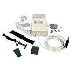
The AL-1 Alert Link Nurse Call Pull Cord Interface is a wireless personal alert receiver designed for use with existing nurse call annunciation systems. In a typical installation, the receiver is used in the place of, or in conjunction with, a standard pull cord to activate a corridor light, bed light, room light, and any audible devices to indicate the need for assistance. Up to 32 wireless transmitters can be programmed to activate each receiver.
Three indicators on the front of the receiver display the system status. The green POWER indicator lights when power for the receiver is present. The yellow SERVICE indicator lights if a transmitter has sent a low battery signal. The red ALERT indicator lights when a transmitter has been triggered, showing that the receiver's outputs have been activated.
Pressing the RESET button on the top of the receiver for less than two seconds will reset any transmitter low battery indications. Pressing the RESET button for more than three seconds will clear the ALERT indication and reset the relay outputs if in the latched mode.
The receiver contains four normally open 1-amp relay contacts that close when activated. One relay provides an isolated output. The three other relays are isolated when open and have a common return. The receiver relays can operate in normal or failsafe mode. In normal mode, the relays will energize when the receiver is triggered. In failsafe mode, the relays are energized continuously until the receiver is triggered. Failsafe mode supervises the system by causing the outputs to activate if power is removed from the receiver. Both modes provide normally open outputs.
Power for the receiver is supplied by a plug-in transformer. The receiver can be mounted directly to a wall or to a single-gang electrical box with the hardware supplied.
Customers Who Bought This Item Also Bought


|
There are no product questions at this time. Search Tags |
Buyer ReviewsWrite a Review There are no buyer reviews at this time. Be the first to review this item! |
Trending Products